This page is meant to examine the role I’ve played in projects in much greater detail to understand constraints, methods, decisions, etc.
RC Glider “Summer Means New Love”
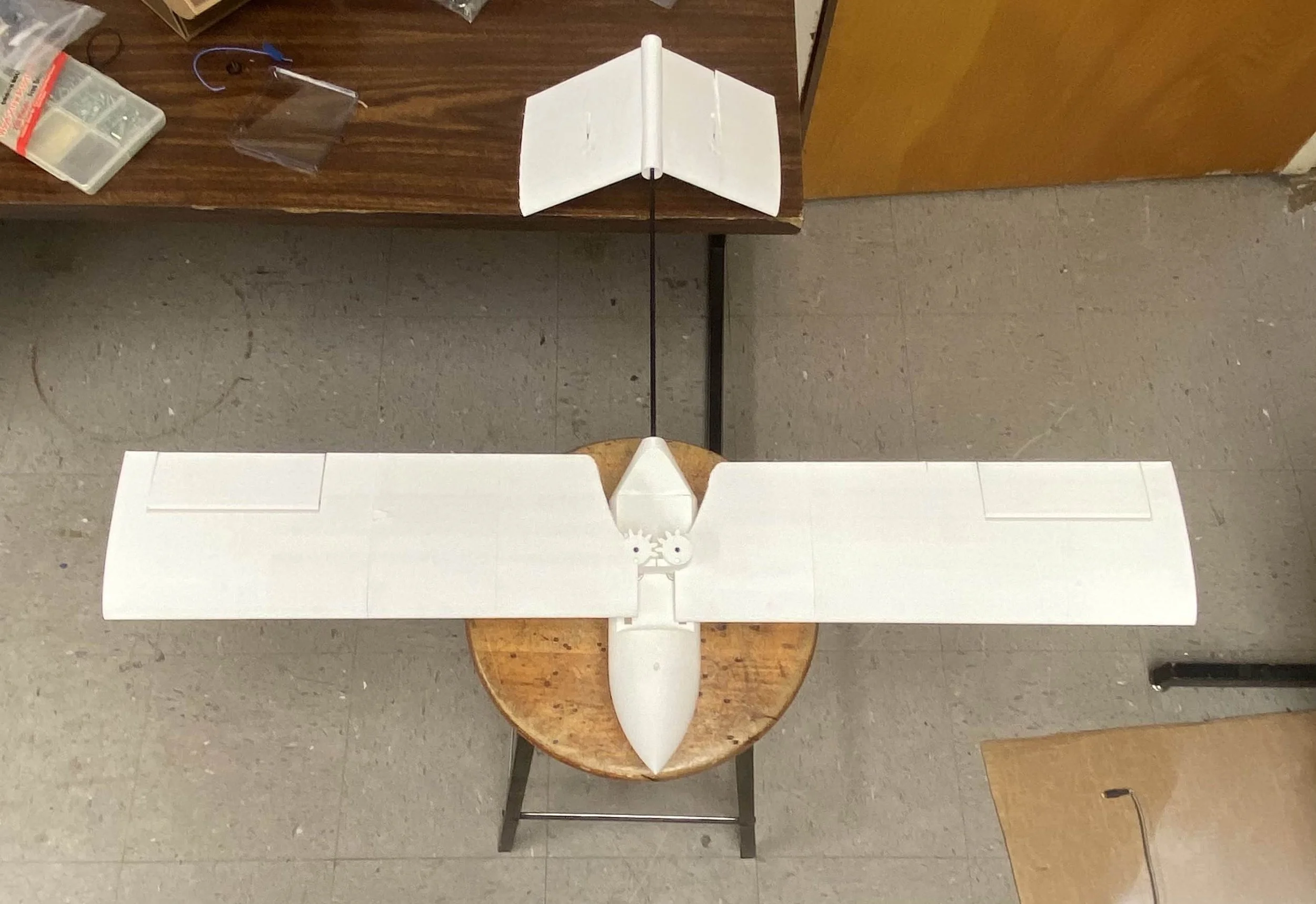
Previous to this project, I had no interest in the aeronautics side of aerospace engineering with a total flight time of about 5 minutes on a single RC aircraft. However, after leading this project since August 2024 I’ve gained an enormous amount of knowledge in aircraft design, simulation, electronics, and testing along with a great respect for the RC flying community and a new perspective on aerospace engineering.
In Summer 2024, the KSU Rocketry Team (KRT) was planning on competing in the NASA Student Launch Challenge ( NASA SLI), where a specific payload challenge is a main draw. This year’s competition tasked teams to create a capsule capable of transmitting at least 3 points of data after landing. Considering this was KRT’s first ever competition with schools like MIT, Purdue, Georgia Tech, and Notre Dame also competing, the team decided on a deployable glider. This project would significantly challenge the team, but would allow us to grow as engineers, showcase KSU engineering on a national stage, and provide many potential applications such as search and rescue, agricultural surveying, ocean data collection, etc. As summer ended, I was chosen to lead the glider sub team as I had taken the initiative on researching potential designs and resources.
As glider sub team lead, my first action was to ensure the 4 other students working with me fully understood the constrains of NASA SLI by thoroughly understanding the rules handbook provided by NASA. Afterwards, we consulted with the Design and Recovery team (which I was also leading at the time) to come up with a final list of constraints and necessary features the glider must have. These included space for sensors and an antenna per the payload challenge requirements, fitting within our planned 6 inch diameter rocket, deploying at apogee (this was later changed to 400 ft above ground level), and achieving a theoretical glide ratio of 10:1. At this point, I proposed whichever design we went with should be mostly 3d printed to allow for quick iteration and simplification of manufacturing, which the team concurred with.
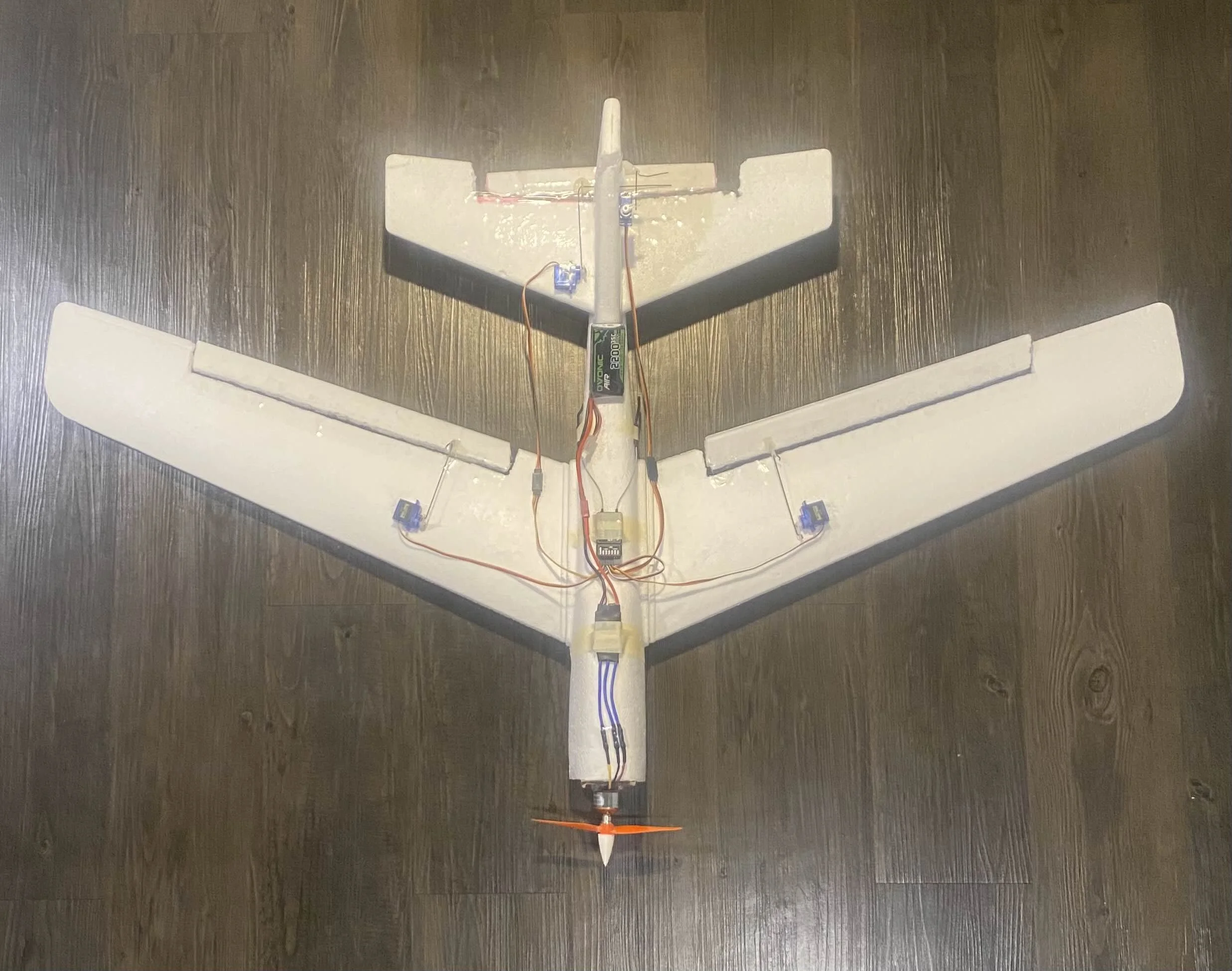
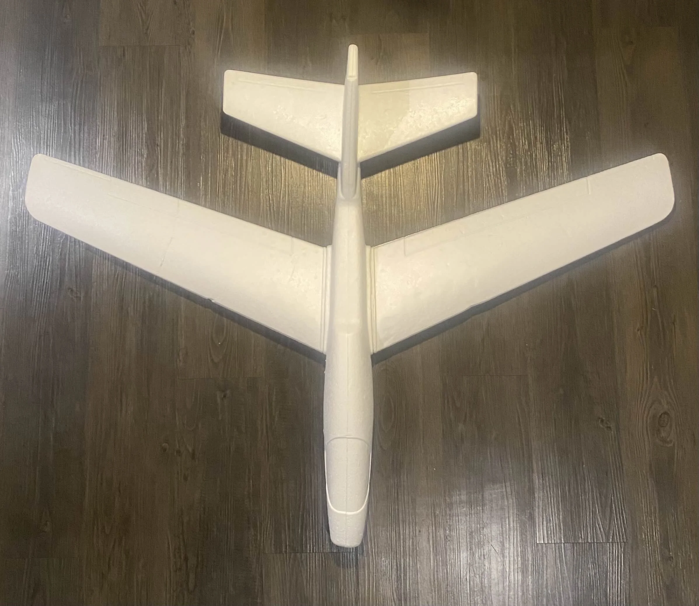
Once we understood the constraints, I gave each member the time to create their own preliminary designs and provided resources such as Aircraft Design: A Conceptual Approach by Daniel Raymer and pointing them to xflr5 and Solidworks while encouraging members to research the pros and cons of their designs. During this, the proposal deadline for NASA SLI was quickly approaching so we decided to simply submit the design I was working on since we could change it afterwards. Once the Preliminary Design phase of the competition started, I called the team came back together to discuss our designs. The team, which had grown to 8 total members now, presented designs such as flying wings, delta wings, and even a Rogallo wing configuration. After conducting trade studies and feasibility studies, the team decided on accepting my design which planned to feature a high folding wing like a glide bomb and an inverted v-tail like a MQ-1 Predator drone. After conducting additional trade studies for each subsystem configuration, the design of the second picture to the right was submitted for the Preliminary Design Review. The decision to go with my design informed many of the rest of our design decisions such as a 5.5 inch chord length, the sizing of the v-tail, dihedral angle of wings, distance between wing and tail, length of wings, etc. When I presented the teams work to a panel of NASA engineers and subject experts, we were given full approval of our progress on the glider, but were asked to change the deployment altitude to 400 ft.
The main focus of the Critical Design Review was design optimization, manufacturing optimization, and simulations. At this point I split the team into three sections for electronic selection and purchase, design and manufacturing, and simulations. Electronics were selected based on reliability, weight, and cost. Design optimization was done through xflr5, modeled in the CAD through Solidworks, and verified with simulations. CFD and FEA simulations were done through Solidworks FlowSim and Ansys. Our work was submitted for the Critical Design Review, but unfortunately KSU Rocketry had to withdraw from NASA SLI due to issues with the subscale vehicle.
Since the team’s withdraw, the glider has been continuing on as a flagship project. We are currently in the middle of final manufacturing and testing while collaborating with aerospace professors to conduct a drone drop test at 400 ft. This page will be updated as progress continues. Glider Documentation (these are the sections I was directly involved in or wrote myself)
For each project I lead or create, I have made it a tradition to name it after a song from my favorite band, The Beach Boys. I chose “Summer Means New Love” as I believe it is they’re best instrumental track with a personal connection and a striking name. The track can be found here.


Class Competition Car “Spirit of America”
A required class for all mechanical engineering majors at KSU is an “Intro to Mechanical Engineering” class. It is meant to introduce some of the fundamental topics of engineering such as statics, thermodynamics, heat transfer, etc. as well as class-wide projects to apply our skills. When I took this class over the summer, the final project was a group competition to design and manufacture a vehicle capable of being launched from a rig with the goal of reaching the farthest distance. Constraints for this project included having the vehicle weigh a minimum of 3 lbs, having at least one 3d printed part, no electronics or active control, and a passive steering / stabilizing mechanism. Additionally, because this was a summer class we were only given one and a half weeks to complete the entire project along with a report and presentation.
My team of 4 was formed from a previous project and our first action was to create hand-drawn sketches of our ideas on Tuesday. On Thursday, we compared our designs, filled out design matrices, and decided on a mix of my friend Luke’s and my design. At the end of class, our professor showed us the rig the vehicle would be launched from, which gave me an alternate design idea. My friend Luke had been involved in KSU Motorsports and had previously told me how they used inverted airfoils for stability and downforce. I decided to combine this with my knowledge of aerospace from KSU Rocketry and the early ideas of the RC Glider to propose a new design which would have the entire vehicle be an inverted airfoil. I also proposed to have a vertical stabilizer for passive steering and having the entire vehicle be entirely 3d printed including the wheels. My team agreed to take on my idea and designated me as team captain. Before leaving, I decided to split our group into two teams, with two members focusing on the report / presentation while Luke and I focused on design and manufacturing. Over that weekend, I designed the first iteration in Solidworks and 3d printed the vehicle out of PLA with the wheels and bumper printed out of TPU.
The following Tuesday, teams were allowed to test-launch their designs before the competition on Thursday. The first iteration preformed far below expectations, constantly drifting off course, barely making it through the opening in the rig, and the wheels causing lots of friction. This was the team’s lowest point as we weren’t sure if we could even compete for Thursday’s competition. When the team came together after class, we concluded many of the issues came from the wheels and we should instead use skateboard wheels as well as shortening the length of the vehicle. Over that night and Wednesday, I redesigned the CAD and printed out the final iteration while consulting and updating the rest of my team. That Thursday, we ended up taking first place in our class and achieving a final longest distance of 161 ft. That night we were able to submit our report and presentation which would be presented the next Tuesday. On Tuesday as we practiced for our presentation, we learned from a professor that we had actually broke the entire school record. Each semester since, roughly 225+ students across 45+ teams compete in this competition and I am proud to say my team continues to hold the record. Team Presentation
This project was named after The Beach Boys’ song “Spirit of America” which details the land-speed record broken by Craig Breedlove in 1963. Although our vehicle didn’t break a speed record, I believed the name was fitting and was partially in honor of Craig Breedlove’s passing roughly a year earlier. The track can be found here.
Similar to the previous project, this was a joint effort to create a flight computer to control a TVC mount and a theoretical Thrust Vector Controlled rocket. Criteria for the flight computer were capabilities for data collection, data processing, controlling two servos, firing pyrotechnic channels, and storing data. In my research for this project, many hobbyist who took on TVC built custom flight computers themselves. Due to this and the opportunity to greatly enhance my electronics skills I also choose to create a flight computer. I choose to use the free software EasyEDA and began by following a couple tutorials on Youtube to familiarize myself with PCB design, component selection, and routing. For the first iteration, I decided to use an Arduino Nano because I was familiar with Arduino and the Integrated Development Environment. I also used all well-known through-hole components for easier manufacturing and troubleshooting. After routing, finalizing the layout, and ordering the PCB, I began soldering and manufacturing. At some point during this, I believe I accidently shorted a connection or somehow damaged the board as I could not power up the board trough the battery connection, directly connecting to the Arduino Nano, or any other method I tried to revive the board. The process of the first iteration left me exhausted, so I decided to take some time to focus on the TVC mount and come up with code for the flight computer.
A couple weeks later, I began designing the second iteration of the board. To further help my skills, I followed more tutorials for PCB design and component selection while picking up some helpful tips such as adding capacitors to even out the power source and adding multiple discrete testing LEDs. During this time, I also compiled code for testing all the sensors, servos, and pyro channels as well as a static fire program using the Arduino IDE with bread boards. After new-found knowledge and confidence in my skills, I redesigned the PCB, rerouted the board, and ordered the new board with it’s components. I also created a scaled-down version of the board to do low-risk testing and design confirmation. This time for manufacturing, I used pin connectors so that each sensor could be removed and swapped as needed decreasing the chance of failure. I also made sure to properly ground my workplace and only solder on a rubber mat to prevent any shorts.
The second iteration exceeded my expectations and worked almost perfectly for every task I needed it to do. The largest improvement I could make is increasing the voltage that the pyro channels are fired at, but since the goal of this project didn’t require the pyro channels, I was content with making this the final iteration. The sensor testing code I wrote correctly collected and stored data on temperature, pressure, gyro measurements, etc. to an sd card. The code for the static fire worked correctly as it actuated the servos in a circular pattern even during the motors firing and ejection charge. Overall, I am very happy with the outcome of this project as I learned lots of electronics and PCB design with no formal classes or background.
The Project is named after both the song “Shut Down Part II” and the album Shut Down Volume 2 by The Beach Boys. After the success of The Beach Boys’ third and fourth studio albums along with their single “Shut Down” Capitol records released a compilation album called Shut Down which featured many of The Beach Boys’ popular car songs. In response, The Beach Boys named their next album which featured lots of car songs Shut Down Volume 2. The TVC mount and flight computer were named after this series of interconnected songs and albums and not necessary the content of the songs themselves. I also thought it was appropriate because this happened in the early career of The Beach Boys, and this was the first major aerospace project I dedicated significant time to and completed. The album can be found here and the song here.
Talon I Rocket
In June of 2024, the Design and Recovery lead for KSU Rocketry had to step down due to scheduling conflicts. At the time, there were no qualified sub team members with enough experience in designing, building, or flying rockets. I had just achieved my level 2 high power rocketry certification with the National Association of Rocketry and had the second-most experience, so I was appointed by the President to serve as interim Design and Recovery lead until we could build enough member experience to let someone else take the role. One of my primary responsibilities during this time as to lead the design and manufacturing of our subscale rocket for NASA SLI. NASA requires each team participating to create a <75% scale rocket to function as close as possible to their submitted designs by the Critical Design Review deadline.
After submitting our Proposal and Preliminary Design Review, the team presented our work to a panel of NASA engineers and subject experts. Thankfully, by that time in October I had found a member with enough built-up experience to take the role of lead and was able to present for me. I had agreed with the new lead to continue leading the technical aspects of the sub-team until the Critical Design Review and the launch of the subscale. Therefore, I continued leading aspects like improving the design of the full-scale and sub-scale from NASA feedback and manufacturing the subscale. I was able to reduce the weight of the sub-scale by 1.72 pounds / 24% and save $280 for the motor, but materials had already been ordered so I couldn’t change the design too radically.
By the end of October, we had received all necessary materials to build the sub-scale, however the team still did not have a workshop space despite being promised one by the school in July. With no safe place to construct or store materials, we were forced to delay the beginning of construction. Finally in mid-November we were able to move into a workshop and could begin manufacturing. During the delay, I was still active in leading efforts for manufacturing by scouting locations on campus we could use for manufacturing such as a maker-space and woodshop with the necessary tools. Additionally, I created a 13 page document (this has some humor and inside jokes) with material checklists for diameters, weights, etc. along with detailed step-by-step manufacturing procedures. Along with these, I also created 9 auxiliary parts I designed in Solidworks and 3d printed to help with manufacturing such as a fin aligner and drill hole guides.
In order to stay in the NASA SLI, we had to have a successful sub-scale launch by February 7th. Even as manufacturing began, we faced multiple issues with Fall break just a week after getting the workshop in order with finals week and the end of the semester directly after. We were able to persevere as I encouraged good communication and consistent updates on manufacturing meeting times and progress. By following the build procedures with careful planning, we were able to complete building, painting, electronics, parachutes, testing, etc. by our December 12th deadline as we planned to launch on December 14th in Huntsville. Unfortunately, our misfortunes continued as the December 14th launch was cancelled due to weather as well as our back up dates of January 4th and January 11th. We were able to attend a last minute make or break launch on January 25th, but were unfortunately able to launch due to issues with electronics, rail buttons, and the motor ignitors.
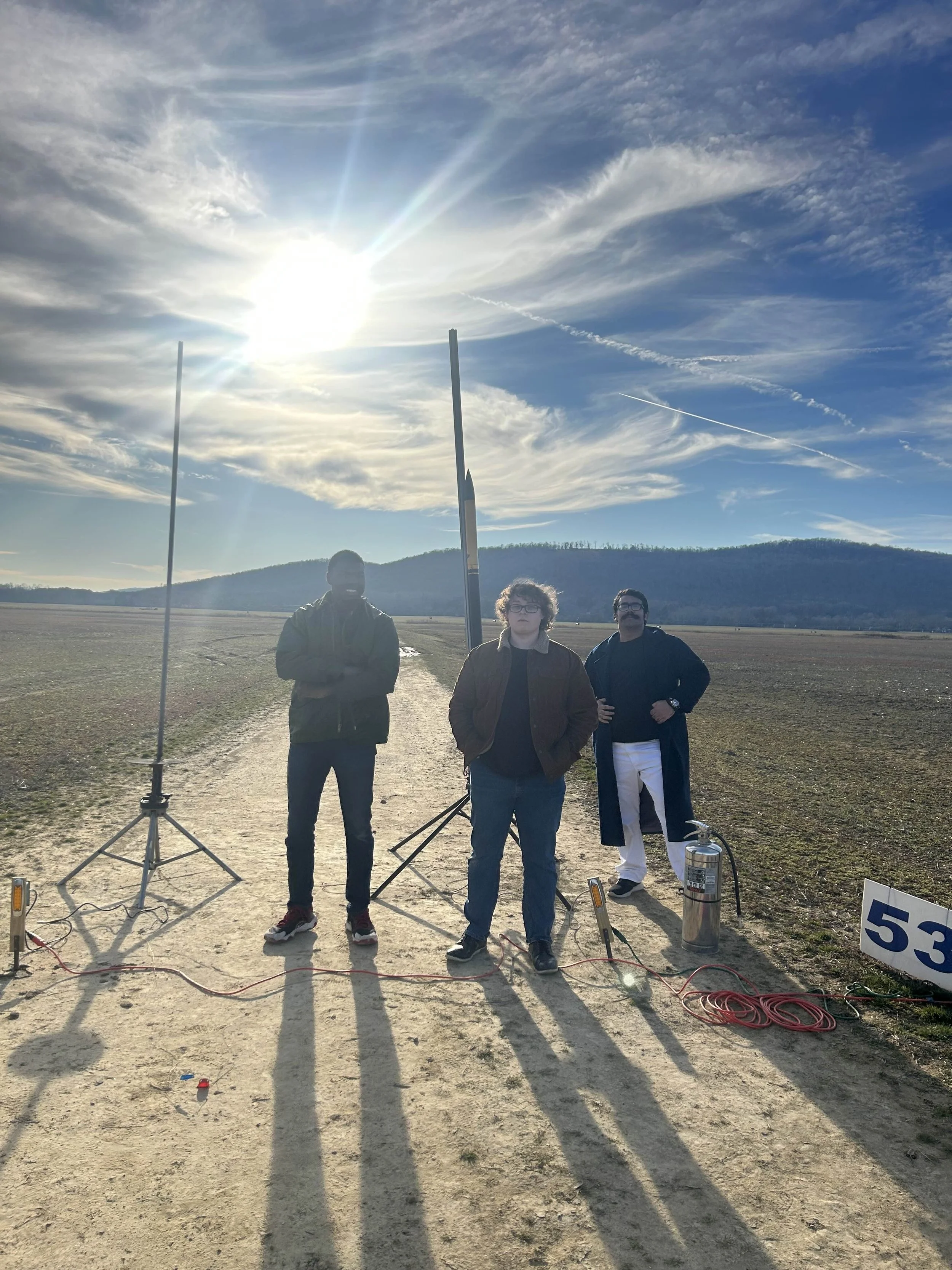
On March 22nd, Talon I was launched for the first time and had a successful launch and recovery, reaching within 125 ft of the simulated apogee of 5250 ft. The only caveat is that the nose cone was lost on decent and we were not able to find it. Even with the failed launch attempt and lost nose cone, I am very proud of the work the team was able to do with very limited resources in such a short time. Everyone involved including me learned so much through this process that we will bring into our next rocket, Talon IV. I am extremely grateful to KSU Rocketry’s president Sebastian for trusting me to lead our first team rocket from design to launch. Design and Recovery Documentation (these are the sections I was directly involved in or wrote myself)

Talon IV Rocket
Beyond Talon I, another one of my major responsibilities during my time as interim Design and Recovery lead was leading the design and simulation of our full-scale rocket Talon IV. For NASA SLI, the vehicle itself is the most important aspect of the competition as it houses the payload, avionics, and all systems associated with them. Additionally, this was the first team rocket KSU Rocketry had ever seriously attempted to create, meaning the vehicle had the most associated work in manufacturing, testing, and launch preparation.
When I began in June, my first action was to encourage members to explore a software called OpenRocket which is used for designing and simulating rockets. I created a 3-part video series totaling over 2 hours covering every aspect of the software. Part 1 | Part 2 | Part 3. Additionally, I made a video covering level 1 high power rocketry certifications to educate members and encourage them to achieve their own certification.
Once the semester began, I had multiple sub team and general body meetings be dedicated solely to understanding the rules of NASA SLI, the goals of the team, the specific roles of the sub teams, and the sub team needs for the vehicle. As this was happening, I began tasking members with designing their own rockets following the criteria of NASA and the team. By late September we had preformed trade studies on members’ designs and configurations to come to the design seen in the second picture. This design ended up taking many of it’s ideas from the former Design and Recovery lead with a few of mine and other members’ ideas integrated in. However, the first proposal was due in September so an early design was used. After PDR submission in late October, the team presented to a panel of NASA engineers and subject experts in mid-November. NASA gave constructive criticism on the vehicle and improvements we could make such as optimizing space and decreasing weight with a due date of the CDR to implement the changes. I had already found another member to take over the Design and Recovery lead position, but I still took on leading many of the technical aspects including revising the design. I changed many aspects of the design such as decreasing the fins from 6 to 4, reducing the electronics bay size, lengthening the nose cone, and switching the motor. These changes reduced the length by 1.32 ft, decreased the wet mass by over 5 lbs., and saved over $400 in material. NASA was very satisfied with these changes and I began compiling a bill of materials for the full-scale which was ordered late January.
In addition to my responsibilities with Talon I and Talon IV, I also took large initiatives for the documentation of the competition. Starting in the summer, I compiled the proposals, preliminary design reviews, critical design reviews, and flight readiness reviews of over 10 universities who previously competed in NASA SLI. These examples became critical to inform the team on documentation decisions such as syntax, formatting, pictures, information to include, document length, etc. that were no doubt paramount to our acceptance. From Late August to mid-September I took initiative to help organize the sub teams to write their respective documentation. To assist with this, I personally created a template with correct formatting, dates, tables of content and figures, and sections. I also created an outline document to act as an information / brainstorming resource which continued into the PDR and CDR. I continued assisting the writing efforts for the PDR, but took a step back for the CDR to focus on the glider section. After each documentation deadline, I also lead a general body meeting to review the materials and identify what we could improve on.
Since the CDR and withdrawing from NASA SLI, I have fully stepped down from being Design and Recovery lead, and the full-scale is now planned to be used a payload launcher for student’s payloads. Design and Recovery Documentation (these are the sections I was directly involved in or wrote myself)
Low-Budget Beginner RC Plane “Getcha Back”
This project began as an idea to improve the education and experience with RC electronics and principles of flight for the glider sub team of KSU Rocketry. Over winter break 2024 I began looking for a relatively cheap, easy, and hands-on project for those new to RC aircraft since I knew there would be lots of manufacturing and electronics work in the upcoming Spring semester. I found this video, which inspired me to use a foam glider and convert it into an RC plane. I found a cheap $10 foam glider from Hobby Lobby, a $30 RC electronics from Amazon, and a $50 receiver and transmitter from Amazon. This meant that for under $100, a member could have all the necessary components to make their own plane and keep it with the expectation of a battery they would buy themselves. The foam glider and cheap components also ensured not much value was lost when a member inevitable crashed it since it could always be easily replaced or repaired. Materials for 3 kits were ordered in January along with the full-scale and glider orders. When materials arrived, I put together the kit by creating control surfaces from the existing foam with general rule of thumb calculations and simply surface mounting the electronics. After a few test flights, some crashes, and lots of hot glue I was able to get the plane flying well with good speed and stability. The two left-over kits were built by other members with hindsight from my kit and now those kits stay in members’ houses, ready to fly at anytime. This experience not only built knowledge with RC electronics and planes, but also helped build a stronger relationship with KSU Aerial Robotics as they also helped build the other 2 kits. I enjoyed this short but sweet project and would love to continue doing it in the coming semesters.
This project was named after “Getcha Back” by The Beach Boys from their self-titled 1985 album. The name embodies the “fly, break, repair, fly again” attitude I was aiming to achieve which I believe I did. At this point, I think my plane might be more hot glue and tape than foam.
Thrust Vector Control Mount “Shut Down”
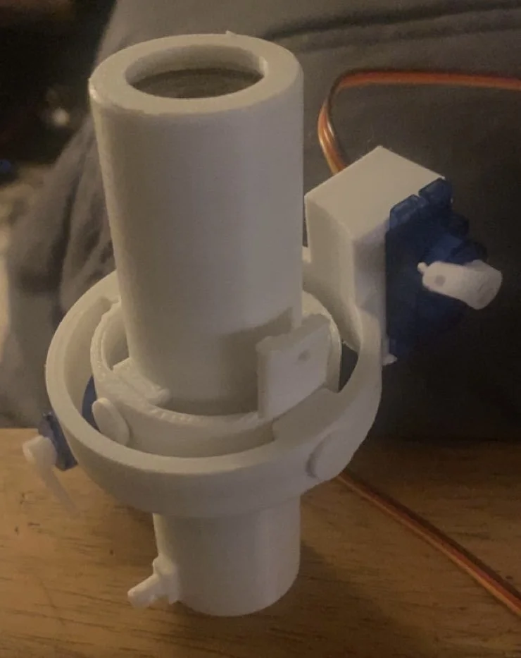
One week before graduating high school, I found a YouTube video from BPS.Space where he landed an amateur rocket just like SpaceX using Thrust Vector Control (TVC). This inspired me to take on a summer project to create a TVC mount capable of actuating up to 10 degrees each direction. Additionally, I was inspired by BPS.Space’s AVA to create a flight computer capable of data collection, processing, handling two servos, firing pyrotechnic channels, and storing data. I began by researching other hobbyists who had attempted TVC and noting their techniques. From my research, I decided to make the TVC mount with a center engine sleeve with two rings around it with a servo on each ring to actuate the sleeve and inner ring. I also decided on making the mount entirely 3d printed to allow for rapid iteration and easy manufacturing. For the first few iterations, I attempted to literally have every single component 3d printed, but the main purpose was to figure out sizing tolerances, strength, mechanics, etc. After the first 3 iterations, I had found a general layout I was happy with and worked well in testing. At this point I also ditched the literal definition of entirely 3d printed and switched to using screws for connection points.
For the 5th iteration, I placed the actuation points at the greatest distance from the center of gravity for better torque and heavily filleted those points to prevent bending of the PLA. I also made the decision to switch from using pushrods for actuation to custom servo arms and thick rectangular connectors. While reviewing my research, I found many hobbyists who took on TVC had issues with slack caused by the thin pushrods having to move relatively heavy mounts. BPS.Space solved this issue himself by switching to an aluminum mount with metal servo arms and connectors. The thick arms and connectors helped to relieve the slack and wiggle from the mount.
After I was satisfied with the design and movement of the 5th iteration, I also created a fin can for the mount to fit inside of for static fires and a theoretical launch. Around this time I also designed a simple launch pad and 3d printed rocket for the TVC mount and flight computer, but did not fully pursue it as it was beyond the scope and timeline of this project. In early August, the mount was test fired and achieved all the goals I had set out to accomplish including eliminating slack and smooth movement. I fired multiple sized motors that day all of which were successful and didn’t damage the mount or flight computer. This project introduced me to the power of iteration and the vast aerospace resources online I can learn myself.
This project was named after the song “Shut Down” by The Beach Boys from their second studio album Surfin’ U.S.A.. This was due to the song’s double relation to the Shut Down and Shut Down Volume 2 albums which will be explained in the next section. The song can be found here.